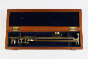
Occasionally I will buy something without bothering to find out what it is first, especially if the price is right. Today’s post concerns a recent acquisition that falls into this category: an unusual pair of dividers with the look of a Planimeterzirkel, beautifully presented in a vivid purple Elliott Brothers case.

Having once missed out on a similarly bargain-priced Planimeterzirkel, this time I decided to follow the unspoken rule of drawing instruments that anything with a dial is bound to have something interesting going on.
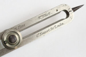
The instrument is helpfully labelled “BAGSHAW’S PATENT”, along with with the manufacturer’s name and “No. 122”, most likely a serial number.

Elliott were in the habit of numbering their instruments made under patent, such as Abney’s level and Richards’ engine indicator, possibly as a way to guarantee that royalties were paid on the precise number manufactured. On the underside of the legs there are some hand-engraved initials, “M.B.W” and “E.D.O.”, along with what is presumably the year “1889”.

It proved a little tricky to locate Bagshaw’s patent, but I finally tracked it down to an 1887 abridged specification – coincidentally dated the 31st of December, 136 years ago today – that reads as follows:
17.962. Bagshaw, W. Dec. 31.
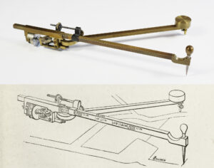
Dividers for measuring the length of the ordinates of steam-engine indicator diagrams. A dial d is mounted on the pivot c of the legs a, b. When the legs are opened a spring pawl e turns the dial an equal angular distance, and return movement is prevented, as the legs are closed, by a spring detent f. h is an index to show the distance the dial has moved. Supposing the diagram to be divided into ten parts, the ten ordinates are measured by the compasses, the legs being closed between each measurement, and the average ordinate is then read off, or obtained from the dial.
So this was yet another gizmo for speeding up the process of finding the mean area of indicator diagrams, which explains its visual similarity to other registering Planimeterzirkel designs as pioneered by Oldendorp in the 1820s.
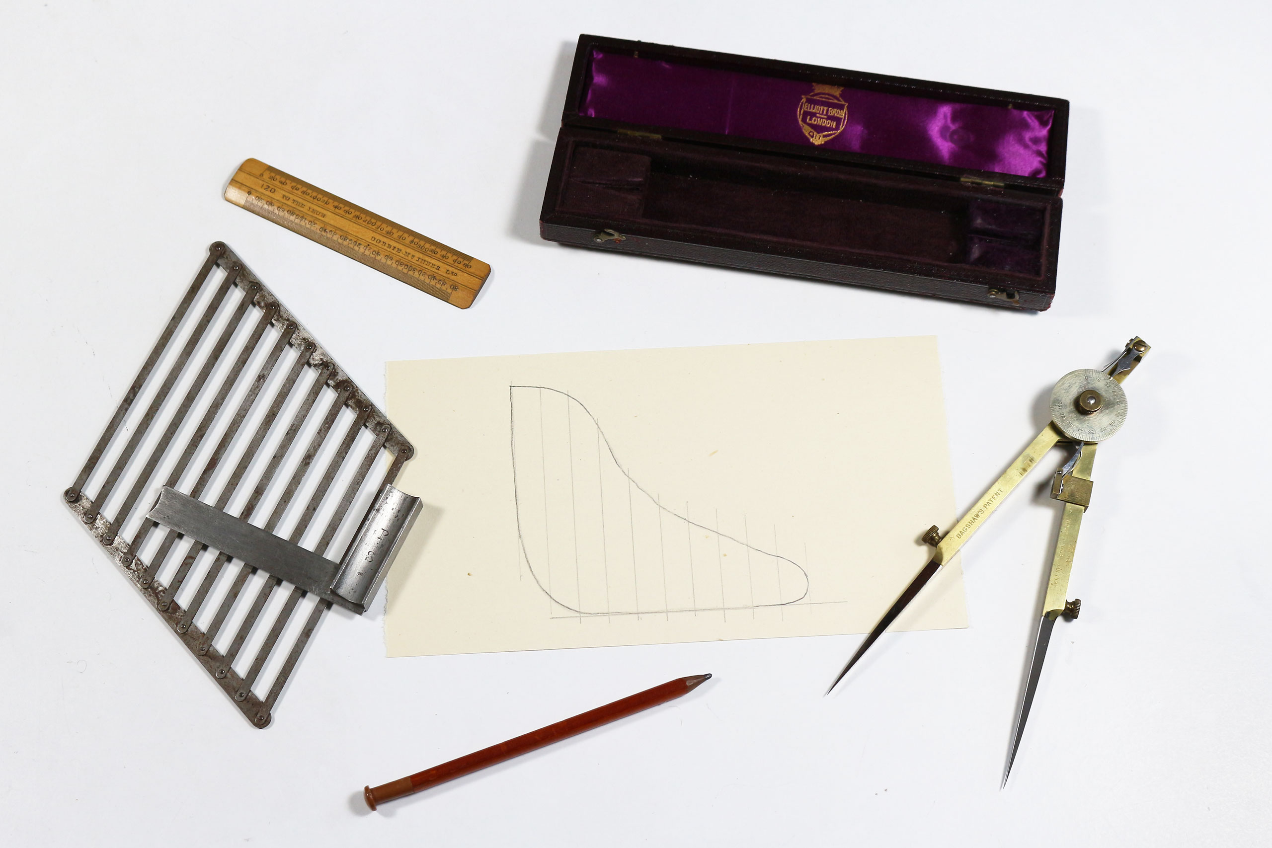
The diagram would still need to be manually divided into ten strips, presumably with something like the special parallel rule that Elliott supplied with their engine indicators, usually found clipped to the underside of the box lid. This was aligned with the diagram by means of a small steel square, as came with my Harling half-set in a cardboard box, and adjusted as shown in this illustration from Pullen’s 1899 book Indicator Diagrams before drawing regular pencil lines across the diagram for measurement.
Depending on the strength of spring used in the engine indicator, the average height would then be scaled using a corresponding boxwood rule, also often supplied in the indicator box. I have photographed a collection of the instruments used – along with my own mock indicator diagram – to give an idea of the whole operation (see main image).
It will be noted that the image which accompanies the patent specification differs in several details from the instrument as manufactured. There is also no mention of one of the more unusual features of Bagshaw’s design, a numbered scale found on the side of one of the legs.

Fortunately, more information about Bagshaw’s dividers can be found in various reviews of the device which began to appear several months after the patent date. The first, published in The Engineer of August 24, 1888 under the heading “Bagshaw’s Diagram-meter”, includes an updated version of the patent illustration and additional details about its construction and use. This article was subsequently reprinted, with minimal alteration – save for the removal of the hyphen in Diagrammeter – in Engineering (October 12, 1888) and The Engineer, New York (November 17, 1888). Finally, another original article was published in The Mining Journal of December 1, 1888 (in which the hyphen is restored), which provides further information, as well as a different illustration showing the side scale.
From these sources, we discover that the diagrammeter was the invention of one Mr Walter Bagshaw of Batley. This would seem to be the son of ironfounder John Bagshaw, who had established the Victoria Foundry in Batley. Today Walter Bagshaw is best remembered for his role in the creation of the Bagshaw Museum, Batley – still open after more than a century – home to an eclectic mix of Egyptology, natural history and ethnology, the core of which was drawn from Bagshaw’s own collections assembled during his world travels.
However, his working life began in much more down-to-earth surroundings. According to The Electricians’ Directory of 1885 and recent genealogical research, Walter completed studies in mathematics and engineering, before gaining experience through his work as a draughtsman at firms including Thomas Beeley’s boiler works at Hyde near Manchester and Kitson & Company’s locomotive works in Leeds. He subsequently became manager of the family business J Bagshaw & Sons in 1875, and was made a partner in 1878 (the 1881 census still describes him as a mechanical engineer).
Bagshaw wrote an influential paper on friction clutches (which were, naturally, manufactured by the family firm), published around the same time as his diagrammeter patent. He also held a range of other patents in his name, including for sluice valves, friction clutches, springs for piston rings, and operating gear for clutches. The firm went on to make automobiles under the marque “JBS” for a brief period between 1913 and 1915.
From this background, it seems likely that the diagrammeter is another example of an instrument originally conceived for the use of its inventor. Bagshaw would have been involved with steam engines of various kinds on a daily basis from the earliest days of his employment as a mechanical engineer, and steam engines would no doubt have been used at the Victoria Foundry itself. It is easy to imagine diagrammeters being issued to the engineers under Bagshaw’s management with the ultimate aim of saving the firm time and money.

The magic of the diagrammeter is the result of a simple trick of ratios, the radius of the dial being precisely one-tenth that of the length of each leg. This means that for every ten measurements taken using the divider points, the distance moved by the perimeter of the dial will automatically be the average of the total (i.e. one tenth of the sum of all ten lengths). It follows that the linear measure marked on the side of the instrument is a projected scale, equal to the units of the dial, which allows the dial reading to be measured with one of the small boxwood scales mentioned earlier, selected to match the indicator spring used.
In this sense, Bagshaw’s device was dedicated to the single task of finding the mean height of an indicator diagram, with no pretences of being a multipurpose tool in any way whatsoever. Compared with the earlier Planimeterzirkel designs that preceded it, the diagrammeter would have been little use for measuring distances on a map, areas of plans, and so on. Indeed, the dial scale seems almost wilfully non-decimal, numbered in multiples of sixteen and subdivided by eight, four and two. The scale length is tailored to accommodate the maximum likely size of ten indicator diagram strips, and consequently stops well short of a full circle, the maximum reading being 192. Oddly, the projected scale on the side of the leg only runs to 160; this may be a consequence of the handles being moved higher up the leg for ergonomic reasons.
As mentioned earlier, the device as supplied by Elliott Bros is not identical to that illustrated in the patent drawing. The Elliotts were known for tweaking the design of the instruments they manufactured, as documented with regard to the computing scale and Abney level among others. The same iterative process of improvement can be seen to have at least begun during the short lifetime of Bagshaw’s diagrammeter.

The round knobs seen on each leg of the patent drawing – intended to be held in the fingers of both hands for ease of manipulation – were clearly found to be impractical, and appear in the later drawings as greatly enlarged discs with long stems. By the time of the illustration that accompanied the last article of December 1888, their design has changed once again, to a form essentially the same as found on the production version. The shape of the dial pointer underwent similar cosmetic changes over the same period, while more structurally significant alterations can be seen in the addition of a separate spring to the pawl, presumably to reduce the chance of slippage.

It is unclear if the projected scale on the side of one leg formed part of the original patent specification, but once again it is only unambiguously described in the final article (although the earlier ones imply that a linear scale may be used with a single dial). The provision of this scale effectively removed the need for the interchangeable dial faces referred to by the earlier articles, and while the dial can still be removed in the device as manufactured, there is no space in the case for additional dials, nor anything to suggest that they were offered. The fact that the steel pointer as built is fixed over the dial, rather than sitting adjacent to it as shown in the drawings, implies that routine replacement of the dial face was no longer a priority.

The name “diagrammeter” may also have come from Elliott Brothers, who seem to have been fairly indiscriminate in their application of the term to any instrument intended for the measurement of indicator diagrams. Before Bagshaw’s design, they had been the manufacturers of Holt’s Diagrammeter, a parallel rule type design that was described in the 1876 Catalogue of the Special Loan Collection of Scientific Apparatus at the South Kensington Museum (I have never come across an actual example of this instrument). Then in 1884, an article from the journal Engineering referred to the version of Amsler’s planimeter with two points for indicator diagrams as being “called a diagrammeter”, again naming Elliott Brothers as the manufacturer (almost certainly in error, as the evidence suggests that all of Amsler’s planimeters were made in Switzerland).
The question remains, who would lavish money on such a device? For all its precision engineering, high quality finish and beautiful silk velvet lined case, this was after all a one-trick pony, capable only of shaving a few minutes off a relatively simple if mundane job.
For the answer, we must turn to the mysterious inscriptions on the other side of the instrument. Usually a three-letter abbreviation would be a non starter for positive identification, with any number of first/middle/surname combinations able to fit the bill; but two three-letter abbreviations, obviously made at the same time, along with a date suggested something other than a simple owner’s name.
In particular, the second triplet “E.D.O” seemed less likely to be a name than some kind of “office”. From here, it was a short step to identify the first three letters “M.B.W.” as the Metropolitan Board of Works, the large local government body that had been responsible for London’s infrastructure – including sewage, streets and bridges, parks, and the fire brigade – for much of the Victorian era. In this context, “E.D.O.” was likely to stand for “Engineers’ Drawing Office”, precisely the place that such an instrument might be found. This would have been headed by Joseph Bazalgette, perhaps the name most associated with the MBW, who was appointed Chief Engineer to the board from its inception. In this role Bazalgette oversaw the design and construction of London’s sewer system, including the Thames embankments which transformed the city’s river frontage. As such, the MBW was responsible for many steam engines, both stationary and locomotive, including the large beam engines of the major pumping stations at Deptford, Crossness, Abbey Mills and Chelsea Embankment.
This all seems straightforward enough, until we get to the date, 1889. During the 1880s, the MBW had become embroiled in a series of scandals that involved corruption, bribery and secret payments to its board members, leading Punch magazine to dub it The Metropolitan Board of “Perks”.
In response to the growing public outrage, the Member of Parliament for Paddington South, Lord Randolph Churchill (father of the better-known Winston), brought a motion to set up a Royal Commission to investigate the Board, which passed on 16 February 1888. In the meantime, other plans were afoot to abolish the MBW and replace it with an elected County Council, the outcome being The Local Government Act 1888 which received Royal assent on 13 August of that year. This Act was due to take effect on 1 April 1889, with the members of its successor the London County Council (LCC) having already been elected as a provisional council on 31 January 1889 in readiness for the imminent handover.
With the writing on the wall, it might have been expected that the first three months of 1889 would have seen the MBW preparing for an orderly transition of power, but nothing could be further from the truth. Instead they continued to award major contracts and take decisions deliberately against the wishes of the LCC, all the while bestowing large pensions on retiring officers and similarly generous salaries to those who would transfer. The final straw was the board’s decision to award the contract for the new Blackwall Tunnel at their very last meeting, which led the LCC to appeal to government. As one contemporary account put it:
“Their latter end was inglorious, for some of their final proceedings excited such dissatisfaction that the Government found it expedient to give them euthanasia ten days before their natural term of life expired.”
The MBW was summarily abolished on 21 March 1889, bringing its tenure of a third of a century to an ignominious end, once again parodied by Punch in a mock “obituary”. Now perhaps it becomes clear why the MBW might have splurged on some fancy Elliott Bros diagrammeters in its last weeks of existence, as the dying regime pursued a scorched-earth policy to spite its successor, while rewarding its loyal footsoldiers with more of the perks to which they had become accustomed. It would be interesting to know how many of those 122 serial numbers (and possibly higher) went to the Metropolitan Board of Works Engineers’ Drawing Office. This would also explain why my example shows little sign of use, still practically as clean and shiny as the day it was handed to its lucky recipient.

At one level, it seems a pity when something turns out to be essentially a redundant artifact, having never fulfilled its intended purpose, but on this occasion the baroque excesses of the backstory more than make up for it!